
Weld Neck
WN · B16.5 · B16.47Tapered hub butt welded to the pipe. The strongest flange, for high pressure and temperature.
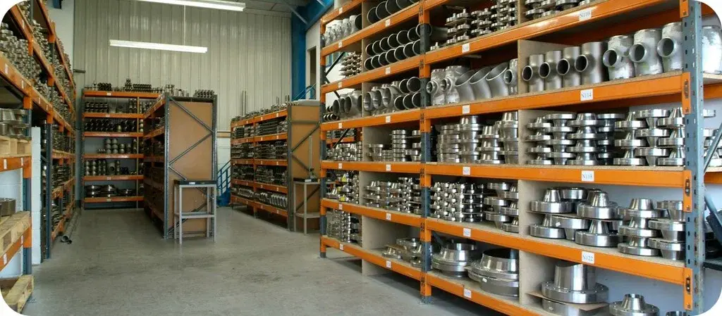
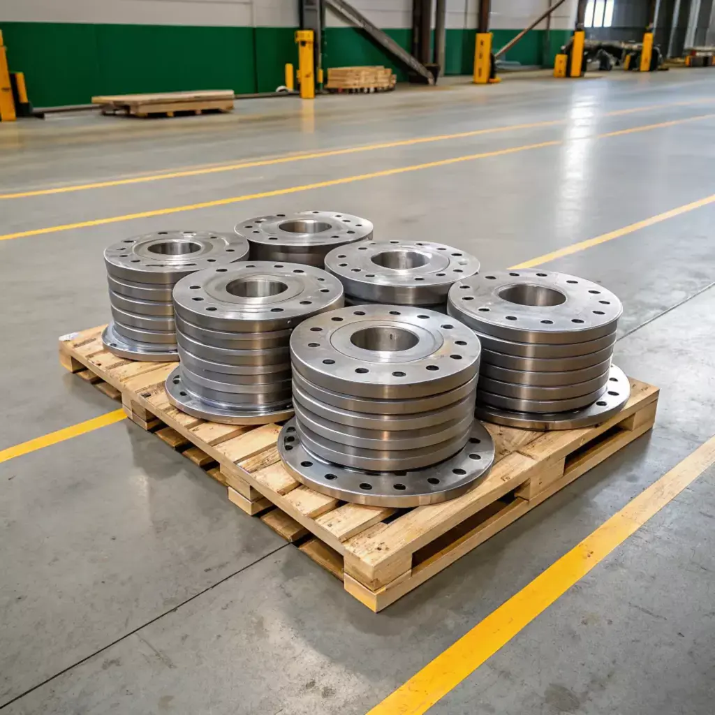
Forged flanges in stainless steel, duplex, carbon steel, alloy steel and nickel alloys — with the pressure ratings, dimensions, facings, grades and bolting you need to specify them.
We supply weld neck, slip on, socket weld, threaded, lap joint and blind flanges, with long weld neck, reducing and orifice flanges and spectacle blinds, in stainless steel, duplex, super duplex, carbon steel and alloy steel — and in nickel alloys and titanium for the lines that need them.
Flanges are supplied in the pressure class, facing and bore that match your pipe, with bolting and gaskets to complete each joint. Every flange is stamped with its grade, size, class and heat number and supplied with a mill test certificate to EN 10204 Type 3.1 or 3.2. When your project needs independent verification, inspection by your nominated agency is carried out before dispatch.
How the flange joins the pipe decides its strength, its cost and how easily the joint is made up. Each drawing shows the flange from the side, with the pipe it takes.
Tapered hub butt welded to the pipe. The strongest flange, for high pressure and temperature.
Slides over the pipe and is fillet welded inside and out. Economical and easy to align.
The pipe sits in a socket and is fillet welded outside. For small-bore, high-pressure lines.
Screwed onto the pipe with no welding — for areas where welding is not allowed.
A loose flange behind a stub end. Turns to line up bolt holes, and can be carbon steel on an alloy line.
A solid disc that closes the end of a line, a nozzle or a test point.
A weld neck with a long straight barrel, used as a nozzle on vessels and columns.
A large flange bored for a smaller pipe, to change size at the joint.
A pair of weld neck flanges with pressure taps, holding an orifice plate for flow measurement.
A blind and a spacer joined by a web. Swung round to isolate a line, or to open it.
The gasket seals on the face of the flange, so the facing and its finish must suit the gasket. Both flanges of a joint must have the same facing.
The gasket area stands proud of the bolting circle: 1.6 mm high for Class 150 and 300, 6.4 mm for Class 400 and above. The most common facing.
The whole face is flat, with a full-face gasket. Used when mating cast iron, bronze or plastic flanges that could crack under a raised face.
A machined groove holds a solid metal ring gasket. For high pressure and temperature, typically Class 600 and above.
A narrow tongue on one flange fits a groove in the other, holding the gasket captive. Used on pump covers and valve bonnets.
A wide raised face on one flange fits a matching recess in the other, locating the gasket.
Raised faces are machined with a spiral or concentric serration of 3.2 to 6.3 µm Ra, so the gasket grips. Smooth finishes are made to order.
A flange's class is a designation, not a pressure. The working pressure it allows depends on the material and falls as the temperature rises. These are the ASME B16.5 ratings for carbon steel A105, Material Group 1.1.
bar · maximum working pressure, Group 1.1
Each step up in class raises the allowed pressure; a Class 2500 flange carries more than twenty times the pressure of a Class 150 flange.
bar · maximum working pressure, Group 1.1
Above about 400 °C the rating of carbon steel drops quickly. For hotter service, alloy steel flanges keep their rating to higher temperatures.
| Temperature, °C | Class 150 | Class 300 | Class 600 | Class 900 | Class 1500 | Class 2500 |
|---|---|---|---|---|---|---|
| −29 to 38 | 19.6 | 51.1 | 102.1 | 153.2 | 255.3 | 425.5 |
| 50 | 19.2 | 50.1 | 100.2 | 150.4 | 250.6 | 417.7 |
| 100 | 17.7 | 46.6 | 93.2 | 139.8 | 233.0 | 388.3 |
| 150 | 15.8 | 45.1 | 90.2 | 135.2 | 225.4 | 375.6 |
| 200 | 13.8 | 43.8 | 87.6 | 131.4 | 219.0 | 365.0 |
| 250 | 12.1 | 41.9 | 83.9 | 125.8 | 209.7 | 349.5 |
| 300 | 10.2 | 39.8 | 79.6 | 119.5 | 199.1 | 331.8 |
| 325 | 9.3 | 38.7 | 77.4 | 116.1 | 193.6 | 322.6 |
| 350 | 8.4 | 37.6 | 75.1 | 112.7 | 187.8 | 313.0 |
| 375 | 7.4 | 36.4 | 72.7 | 109.1 | 181.8 | 303.1 |
| 400 | 6.5 | 34.7 | 69.4 | 104.2 | 173.6 | 289.3 |
| 425 | 5.5 | 28.8 | 57.5 | 86.3 | 143.8 | 239.7 |
| 450 | 4.6 | 23.0 | 46.0 | 69.0 | 115.0 | 191.7 |
Swipe the table sideways to see every class
Pressures in bar gauge. Other materials have their own tables in ASME B16.5; the group for each common forging grade is listed below.
| Group | Flange grades |
|---|---|
| 1.1 | A105 · A350 LF2 |
| 1.9 | A182 F11 Cl. 2 |
| 1.10 | A182 F22 Cl. 3 |
| 1.15 | A182 F91 |
| 2.1 | A182 F304 · F304H |
| 2.2 | A182 F316 · F316H |
| 2.3 | A182 F304L · F316L |
| 2.4 | A182 F321 |
| 2.5 | A182 F347 |
| 2.8 | A182 F51 · F53 · F55 |
Flanges are forged, so each material has a forging specification. Choose a family to see the flange grades, and the pipe grade each one is welded to.
Stainless flanges are forged to ASTM A182, where each grade carries an F prefix. The grade matches the A312 pipe it is welded to.
| Grade | UNS | Pipe | Where it is used |
|---|---|---|---|
| F304 / F304L | S30400 / S30403 | TP304 / TP304L | General process, water and food lines. |
| F304H | S30409 | TP304H | High-temperature service above 525 °C. |
| F316 / F316L | S31600 / S31603 | TP316 / TP316L | Chemical, pharmaceutical and coastal plants. |
| F317L | S31703 | TP317L | Pulp, paper and flue-gas service. |
| F321 / F321H | S32100 / S32109 | TP321 / TP321H | Stabilised for 400–800 °C service. |
| F347 | S34700 | TP347 | Refinery and high-temperature steam lines. |
| F310 | S31000 | TP310S | Furnace and heat-treatment piping. |
| F904L | N08904 | N08904 | Sulphuric and phosphoric acid lines. |
Duplex and super duplex flanges for seawater, offshore and chemical lines, forged to ASTM A182.
| Grade | UNS | Pipe | Where it is used |
|---|---|---|---|
| F51 (2205) | S31803 | A790 S31803 | Chemical, offshore and desalination piping. |
| F60 (2205) | S32205 | A790 S32205 | As F51, with tighter chemistry. |
| F53 (2507) | S32750 | A790 S32750 | Seawater and high-chloride lines. |
| F55 | S32760 | A790 S32760 | Seawater, firewater and sour service. |
| F44 (6Mo) | S31254 | A312 S31254 | Super-austenitic, for seawater and bleach plants. |
A105 is the standard carbon steel flange. A350 grades are impact tested for low temperature, and A694 matches high-yield line pipe.
| Grade | Service | Pipe | Where it is used |
|---|---|---|---|
| A105 | General & high temperature | A106 Gr. B · A53 Gr. B | The standard carbon steel flange for process and utility lines. |
| A350 LF2 Cl. 1 | Impact tested to −46 °C | A333 Gr. 6 | Low-temperature and cold-climate lines. |
| A350 LF3 | Impact tested to −101 °C | A333 Gr. 3 | 3½ % nickel steel for colder service. |
| A694 F42 – F70 | High yield | API 5L X42 – X70 | Oil and gas transmission pipelines. |
| A516 Gr. 70 | Plate flanges | – | Large, low-pressure flanges and ring flanges cut from plate. |
Chromium-molybdenum flanges for steam and refinery lines. The F grade matches the P grade of the pipe.
| Grade | Composition | Pipe | Where it is used |
|---|---|---|---|
| F5 | 5Cr – ½Mo | A335 P5 | Refinery lines with hot sulphur-bearing streams. |
| F9 | 9Cr – 1Mo | A335 P9 | Higher-temperature refinery and heater piping. |
| F11 Cl. 2 | 1¼Cr – ½Mo | A335 P11 | Steam lines and headers. |
| F12 | 1Cr – ½Mo | A335 P12 | Boiler and steam piping. |
| F22 Cl. 3 | 2¼Cr – 1Mo | A335 P22 | High-pressure steam and hydrogen service. |
| F91 | 9Cr – 1Mo – V | A335 P91 | Main steam and hot reheat lines. |
Nickel-alloy flanges are forged to ASTM B564, which identifies each alloy by its UNS number; Alloy 20 flanges are made to B462.
| Alloy | Flange | Pipe | Where it is used |
|---|---|---|---|
| Monel 400 | B564 N04400 | B165 | Seawater and hydrofluoric acid lines. |
| Inconel 600 | B564 N06600 | B167 | High-temperature and caustic service. |
| Inconel 625 | B564 N06625 | B444 | Seawater, flue-gas and chemical lines. |
| Incoloy 800 / 800H | B564 N08800 / N08810 | B407 | Furnace and petrochemical piping. |
| Incoloy 825 | B564 N08825 | B423 | Sulphuric and phosphoric acid lines. |
| Hastelloy C276 | B564 N10276 | B622 | Wet chlorine and mixed-acid service. |
| Alloy 20 | B462 N08020 | B729 | Sulphuric acid handling. |
Titanium flanges for seawater, chlor-alkali and chemical plant. Lap joint flanges in carbon steel over titanium stub ends are a common way to save cost.
| Grade | Flange | Pipe | Where it is used |
|---|---|---|---|
| Grade 2 | B381 F2 | B861 / B862 Gr. 2 | General corrosion service and seawater lines. |
| Grade 7 | B381 F7 | B861 / B862 Gr. 7 | Reducing acids. |
| Grade 12 | B381 F12 | B861 / B862 Gr. 12 | Crevice-corrosion resistance at higher temperature. |
Copper-nickel flanges for seawater cooling and firewater systems on ships and offshore platforms.
| Alloy | UNS | Pipe | Where it is used |
|---|---|---|---|
| Copper-Nickel 90/10 | C70600 | EEMUA 144 · B466 | Seawater cooling and firewater lines. |
| Copper-Nickel 70/30 | C71500 | B466 | Higher-velocity seawater service. |
Forged aluminium flanges for cryogenic, chemical and lightweight piping.
| Alloy | Temper | Pipe | Where it is used |
|---|---|---|---|
| 6061 | T6 | B241 6061 | General structural and process piping. |
| 5083 | O / H112 | B241 5083 | Marine and cryogenic service. |
Swipe the table sideways to see every column
These are the grades asked for most, not the limit of what we supply. For other families and product forms, see Materials & Grades.
Composition limits for the most common flange grades, in percent by weight. A single figure is a maximum; a range shows minimum and maximum.
| Grade | C | Mn | P | S | Si | Cr | Ni | Mo | Others |
|---|---|---|---|---|---|---|---|---|---|
| Carbon steel | |||||||||
| A105 | 0.35 | 0.60 – 1.05 | 0.035 | 0.040 | 0.10 – 0.35 | 0.30 | 0.40 | 0.12 | Cu 0.40 · V 0.08 |
| A350 LF2 | 0.30 | 0.60 – 1.35 | 0.035 | 0.040 | 0.15 – 0.30 | 0.30 | 0.40 | 0.12 | Cu 0.40 · V 0.08 · Nb 0.02 |
| Alloy steel · ASTM A182 | |||||||||
| F11 Cl. 2 | 0.10 – 0.20 | 0.30 – 0.80 | 0.040 | 0.040 | 0.50 – 1.00 | 1.00 – 1.50 | – | 0.44 – 0.65 | – |
| F22 Cl. 3 | 0.05 – 0.15 | 0.30 – 0.60 | 0.040 | 0.040 | 0.50 | 2.00 – 2.50 | – | 0.87 – 1.13 | – |
| F91 | 0.08 – 0.12 | 0.30 – 0.60 | 0.020 | 0.010 | 0.20 – 0.50 | 8.00 – 9.50 | 0.40 | 0.85 – 1.05 | V 0.18 – 0.25 · Nb 0.06 – 0.10 · N 0.030 – 0.070 |
| Stainless steel · ASTM A182 | |||||||||
| F304 | 0.08 | 2.00 | 0.045 | 0.030 | 1.00 | 18.0 – 20.0 | 8.0 – 11.0 | – | N 0.10 |
| F304L | 0.030 | 2.00 | 0.045 | 0.030 | 1.00 | 18.0 – 20.0 | 8.0 – 12.0 | – | N 0.10 |
| F316 | 0.08 | 2.00 | 0.045 | 0.030 | 1.00 | 16.0 – 18.0 | 10.0 – 14.0 | 2.00 – 3.00 | N 0.10 |
| F316L | 0.030 | 2.00 | 0.045 | 0.030 | 1.00 | 16.0 – 18.0 | 10.0 – 14.0 | 2.00 – 3.00 | N 0.10 |
| F321 | 0.08 | 2.00 | 0.045 | 0.030 | 1.00 | 17.0 – 19.0 | 9.0 – 12.0 | – | Ti 5×(C+N) – 0.70 · N 0.10 |
| Duplex & super duplex · ASTM A182 | |||||||||
| F51 | 0.030 | 2.00 | 0.030 | 0.020 | 1.00 | 21.0 – 23.0 | 4.5 – 6.5 | 2.5 – 3.5 | N 0.08 – 0.20 |
| F53 | 0.030 | 1.20 | 0.035 | 0.020 | 0.80 | 24.0 – 26.0 | 6.0 – 8.0 | 3.0 – 5.0 | N 0.24 – 0.32 · Cu 0.50 |
| F55 | 0.030 | 1.00 | 0.030 | 0.010 | 1.00 | 24.0 – 26.0 | 6.0 – 8.0 | 3.0 – 4.0 | N 0.20 – 0.30 · Cu 0.50 – 1.00 · W 0.50 – 1.00 |
Swipe the table sideways to see every element
Values are shown for reference and follow the specifications named in the table. Limits are revised from time to time, so the edition of the specification on your order, and the mill test certificate supplied with the material, always govern.
Minimum tensile and yield strength and the hardness limits of the common forging grades. Hardness limits matter for sour service, where hard material can crack.
| Grade | Tensile strength MPa | Yield strength, min MPa | Elongation, min % | Hardness HBW |
|---|---|---|---|---|
| Carbon steel | ||||
| A105 | 485 min | 250 | 22 | 137 – 187 |
| A350 LF2 Cl. 1 | 485 – 655 | 250 | 22 | 197 max |
| Alloy steel | ||||
| A182 F11 Cl. 2 | 485 min | 275 | 20 | 143 – 207 |
| A182 F22 Cl. 3 | 515 min | 310 | 20 | 156 – 207 |
| A182 F91 | 585 min | 415 | 20 | 248 max |
| Stainless steel | ||||
| F304 · F316 · F321 · F347 | 515 min | 205 | 30 | – |
| F304L · F316L | 485 min | 170 | 30 | – |
| Duplex & super duplex | ||||
| F51 | 620 min | 450 | 25 | 290 max |
| F53 | 800 min | 550 | 15 | 310 max |
| F55 | 750 min | 550 | 25 | 310 max |
Swipe the table sideways to see every column
Actual test results are reported on the mill test certificate. For sour service to NACE MR0175 / ISO 15156, state it on the order so hardness is controlled and reported.
Outside diameter, thickness, bolting and hub length for weld neck flanges, in mm. The outside diameter, bolt circle and bolting are the same for every flange type of the same size and class.
| NPSinch | ODmm | Thicknesstf, min | Raised facediameter | Bolt circlediameter | Boltsnumber | Bolt sizeinch | Bolt holediameter | Weld neckY, hub length |
|---|---|---|---|---|---|---|---|---|
| Class 150 | ||||||||
| 1/2 | 90 | 9.6 | 34.9 | 60.3 | 4 | 1/2 | 15.9 | 46 |
| 3/4 | 100 | 11.2 | 42.9 | 69.9 | 4 | 1/2 | 15.9 | 51 |
| 1 | 110 | 12.7 | 50.8 | 79.4 | 4 | 1/2 | 15.9 | 54 |
| 1 1/4 | 115 | 14.3 | 63.5 | 88.9 | 4 | 1/2 | 15.9 | 56 |
| 1 1/2 | 125 | 15.9 | 73.0 | 98.4 | 4 | 1/2 | 15.9 | 60 |
| 2 | 150 | 17.5 | 92.1 | 120.7 | 4 | 5/8 | 19.1 | 62 |
| 2 1/2 | 180 | 20.7 | 104.8 | 139.7 | 4 | 5/8 | 19.1 | 68 |
| 3 | 190 | 22.3 | 127.0 | 152.4 | 4 | 5/8 | 19.1 | 68 |
| 3 1/2 | 215 | 22.3 | 139.7 | 177.8 | 8 | 5/8 | 19.1 | 70 |
| 4 | 230 | 22.3 | 157.2 | 190.5 | 8 | 5/8 | 19.1 | 75 |
| 5 | 255 | 22.3 | 185.7 | 215.9 | 8 | 3/4 | 22.2 | 87 |
| 6 | 280 | 23.9 | 215.9 | 241.3 | 8 | 3/4 | 22.2 | 87 |
| 8 | 345 | 27.0 | 269.9 | 298.5 | 8 | 3/4 | 22.2 | 100 |
| 10 | 405 | 28.6 | 323.8 | 362.0 | 12 | 7/8 | 25.4 | 100 |
| 12 | 485 | 30.2 | 381.0 | 431.8 | 12 | 7/8 | 25.4 | 113 |
| 14 | 535 | 33.4 | 412.8 | 476.3 | 12 | 1 | 28.6 | 125 |
| 16 | 595 | 35.0 | 469.9 | 539.8 | 16 | 1 | 28.6 | 125 |
| 18 | 635 | 38.1 | 533.4 | 577.9 | 16 | 1 1/8 | 31.8 | 138 |
| 20 | 700 | 41.3 | 584.2 | 635.0 | 20 | 1 1/8 | 31.8 | 143 |
| 24 | 815 | 46.1 | 692.2 | 749.3 | 20 | 1 1/4 | 34.9 | 151 |
| Class 300 | ||||||||
| 1/2 | 95 | 12.7 | 34.9 | 66.7 | 4 | 1/2 | 15.9 | 51 |
| 3/4 | 115 | 14.3 | 42.9 | 82.6 | 4 | 5/8 | 19.1 | 56 |
| 1 | 125 | 15.9 | 50.8 | 88.9 | 4 | 5/8 | 19.1 | 60 |
| 1 1/4 | 135 | 17.5 | 63.5 | 98.4 | 4 | 5/8 | 19.1 | 64 |
| 1 1/2 | 155 | 19.1 | 73.0 | 114.3 | 4 | 3/4 | 22.2 | 67 |
| 2 | 165 | 20.7 | 92.1 | 127.0 | 8 | 5/8 | 19.1 | 68 |
| 2 1/2 | 190 | 23.9 | 104.8 | 149.2 | 8 | 3/4 | 22.2 | 75 |
| 3 | 210 | 27.0 | 127.0 | 168.3 | 8 | 3/4 | 22.2 | 78 |
| 3 1/2 | 230 | 28.6 | 139.7 | 184.2 | 8 | 3/4 | 22.2 | 79 |
| 4 | 255 | 30.2 | 157.2 | 200.0 | 8 | 3/4 | 22.2 | 84 |
| 5 | 280 | 33.4 | 185.7 | 235.0 | 8 | 3/4 | 22.2 | 97 |
| 6 | 320 | 35.0 | 215.9 | 269.9 | 12 | 3/4 | 22.2 | 97 |
| 8 | 380 | 39.7 | 269.9 | 330.2 | 12 | 7/8 | 25.4 | 110 |
| 10 | 445 | 46.1 | 323.8 | 387.4 | 16 | 1 | 28.6 | 116 |
| 12 | 520 | 49.3 | 381.0 | 450.8 | 16 | 1 1/8 | 31.8 | 129 |
| 14 | 585 | 52.4 | 412.8 | 514.4 | 20 | 1 1/8 | 31.8 | 141 |
| 16 | 650 | 55.6 | 469.9 | 571.5 | 20 | 1 1/4 | 34.9 | 144 |
| 18 | 710 | 58.8 | 533.4 | 628.6 | 24 | 1 1/4 | 34.9 | 157 |
| 20 | 775 | 62.0 | 584.2 | 685.8 | 24 | 1 1/4 | 34.9 | 160 |
| 24 | 915 | 68.3 | 692.2 | 812.8 | 24 | 1 1/2 | 41.3 | 167 |
Swipe the chart sideways to see every dimension
Class 600 to 2500, sizes above NPS 24 to ASME B16.47 Series A and B, and EN 1092-1 PN flanges are supplied to their own dimension tables; send the size and rating and we will confirm.
A flanged joint is the flanges, the gasket, the stud bolts and the nuts. We supply the whole set, matched to the service. The number and size of bolts for each flange are in the dimension chart above.
| Service | Stud bolts · nuts | Typical gasket |
|---|---|---|
| Carbon steel, general service | A193 B7 · A194 2H | Spiral wound, stainless steel with graphite filler, inner and outer rings. |
| Low temperature, to −101 °C | A320 L7 · A194 Gr. 7 | Spiral wound or ring joint, matched to the flange material. |
| Stainless steel lines | A193 B8 / B8M · A194 8 / 8M | Spiral wound, 316L with graphite or PTFE filler. |
| High temperature | A193 B16 · A194 Gr. 4 or 7 | Spiral wound with graphite, or ring joint. |
| Sour service, NACE MR0175 | A193 B7M · A194 2HM | Spiral wound or ring joint in a corrosion-resistant alloy. |
| High pressure, RTJ flanges | A193 B7 · A194 2H | Ring joint, soft iron or stainless: R, RX or BX type. |
Swipe the table sideways to see every column
A starting point for choosing the flange type and facing. The material follows the pipe; the class follows the pressure and temperature.
| Situation | Typical choice | Why |
|---|---|---|
| High pressure, high temperature or cyclic service | Weld neck | The tapered hub spreads stress, and the butt weld can be radiographed. |
| Low-pressure utility and water lines | Slip on | Cheaper and easier to align; lower strength and fatigue life than weld neck. |
| Small-bore, high-pressure lines | Socket weld | Smooth bore and a strong joint without a butt weld. |
| No welding allowed on site | Threaded | Screwed on; for small bore and non-cyclic service. |
| Frequent dismantling or costly alloy lines | Lap joint + stub end | Bolt holes line up easily; the loose flange can be carbon steel. |
| Closing a line or a nozzle | Blind | A solid, bolted closure that can be removed. |
| Positive isolation of equipment | Spectacle blind | Turned to show which way the line is set: open or closed. |
| Flow measurement | Orifice flanges | Pressure taps drilled on each side of the orifice plate. |
| Vessel and column nozzles | Long weld neck | The long barrel forms the nozzle neck. |
| Most process piping | Raised face, serrated | Works with spiral wound and sheet gaskets. |
| Class 600 and above, oil & gas | Ring type joint | Metal ring gasket seals reliably at high pressure. |
| Mating cast iron or plastic flanges | Flat face | Full-face contact avoids cracking the brittle flange. |
Swipe the table sideways to see every column
This guide is for orientation only. The choice of flange, class and material depends on the full service conditions and the governing piping code, and remains the responsibility of the design engineer.
Every flange is traceable to its heat number and leaves with its mill test certificate. These tests are arranged when your order calls for them.
The class is a pressure rating designation under ASME B16.5, not a pressure in psi. The pressure a flange may carry depends on its class, its material group and the temperature. For example, an A105 carbon steel Class 150 flange is rated 19.6 bar at 38 °C, falling to 10.2 bar at 300 °C. See the pressure ratings.
A weld neck flange has a long tapered hub that is butt welded to the pipe, which spreads stress smoothly and allows the weld to be radiographed. It is preferred for high pressure, high temperature and cyclic service. A slip on flange slides over the pipe and is fillet welded inside and out. It is cheaper and easier to align, but has lower strength and fatigue life.
Raised face (RF) is the most common facing and is used with spiral wound and sheet gaskets in most process piping. Ring type joint (RTJ) flanges have a groove that holds a solid metal ring gasket; they are used at high pressure and temperature, typically Class 600 and above, and in oil and gas service. See the facings.
Generally not. ASME B16.5 flanges are made in pressure classes with inch-based bolt circles, while EN 1092-1 flanges are made in PN ratings with metric bolt circles. Bolt circles, bolt sizes and hole counts usually differ, so the two should not be mixed unless the dimensions are checked for the specific size.
For carbon steel flanges in general service, ASTM A193 B7 stud bolts with A194 2H nuts and a spiral wound gasket are the usual choice. Stainless steel lines use A193 B8 or B8M studs with A194 8 or 8M nuts. Low temperature service uses A320 L7 studs, and sour service B7M studs with 2HM nuts. See bolts & gaskets.
Every lot is supplied with a mill test certificate to EN 10204 Type 3.1 or 3.2, traceable to the heat number stamped on each flange, along with any additional test reports ordered, such as ultrasonic testing, PMI or hardness. When third-party inspection is called for, the agency's inspection release note is included. More on our quality & inspection page.
Pipe, fittings, valves and fasteners in matching grades, so every joint comes from one supplier with one set of documents.
Send the type, size, class, facing and grade. We will confirm availability and quote, with bolting and gaskets if you need them, and the mill test certificate and inspection you require.